
Sheet metal design varies drastically compared to solid modeling, requiring specialized drafting and modeling tools that can generate design data helpful for the fabricators. Contrary to solid objects, sheet metal components are fabricated from a 2D sheet through operations like bending, welding and punching to turn it into a 3D object.
This necessitates design engineers to include provisions in the model that they are designing, so that fabricators can convert the design to sheet metal component successfully. The special design requirements as such calls for a CAD system that provides the right tools to the designer that are specific to sheet metal.
With proper drafting and modeling tools, the design can be quickly pushed to shop floor, while wrong ones delay the fabrication process and eventually lead to loss of time, material and profitability. Choosing the right CAD software for sheet metal design is as such highly critical and requires a careful understanding on existing tooling capabilities.
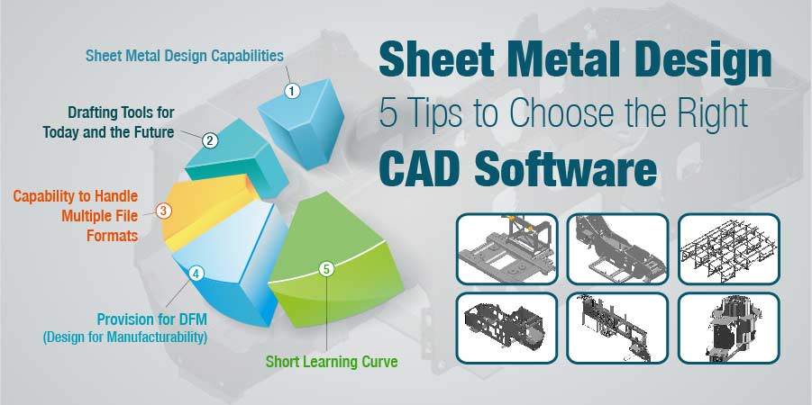
In addition, if there are vendors in the supply chain, there is also a need to select a CAD system that is compatible and offers seamless interoperability. There are five important points however to consider while choosing the CAD software for your sheet metal design requirements.
Sheet Metal Design Capabilities
The very first requirement is gauging the sheet metal capabilities in the CAD system that you are buying. It is important to know that there is no one CAD system that can fulfill all your design requirements. Also, a highly appreciated CAD tools in the market may not work in your favor with the kind of tooling capability you have.
Most CAD modeling platforms available today include sheet metal design features that are easy to use while developing a 3D model. It is also possible to convert solid models to sheet metal components and later develop flat patterns out of it.
There are specialized CAD systems too that are specifically designed for sheet metal work and are much more useful in mass manufacturing organizations. However, these tools do not help much in places where design requirements vary or products are developed according to the customer specifications.
Drafting Tools for Today and the Future
Sheet metal fabrication often involves use of 2D drawings even if the designs are developed in 3D. This is because 3D models do not completely reveal all the details required for fabrication such as dimensions, tolerances, surface finish specifications or notes related to additional processes required after assembly such as surface treatment, etc.
Thus it is important to ensure that the 3D CAD system you select has capabilities to efficiently develop drawings according to the standards that you follow for dimensioning, lettering, tolerances and BOM listing. Also ensure that the drawings you create are easy to export in common formats such as PDF, DXF or DWG, so that interoperability issues with your supply chain vendors are minimal.
There are CAD tools like SolidWorks that also offer model based design (MBD) for manufacturers and fabricators who are on a journey to become digital completely. MBD allows design engineers to add manufacturing information directly onto the 3D model and hence eliminates the use of separate document. This approach helps in reducing errors due to better control over design revisions and helps in keeping the entire development process efficient.
Capability to Handle Multiple File Formats
One of the major considerations for choosing a CAD system for sheet metal design should be on how the software handles file formats. For a large sheet metal product manufacturer or fabricator, this is even more important as there are chances of multiple supply chain vendors involved in the product development. There are chances that design information from each of them would come from different CAD platforms and different file formats.
Managing the design can then be painful as there are chances of models losing the features when they are transferred to your native system. While there are numerous efforts made in the direction of solving this interoperability issues, the best possible solution as of now is to opt for a system that support multiple file formats, so that translation is smooth with lesser chances of missing out any feature. Another option is to try and maintain a uniform CAD system across the supply chain or a uniform file format such as IGES or STEP to reduce errors and rework.
Provision for DFM (Design for Manufacturability)
For sheet metal products, design for manufacturability (DFM) is highly critical and must be kept in mind while developing new designs. Modern CAD tools offer the functionality where a design engineer can check the design for manufacturing feasibility and can validate the design prior to sending it for actual fabrication.
Features such as bend allowances, ribs, chamfers, collars and reliefs can be added to a sheet metal model, so that when the design information reaches to the shop floor, it is easier to give a desired shape with lesser number of change orders.
Short Learning Curve
A feature-packed CAD system can promise enhanced productivity, but that can only happen if it is easy to implement within your own processes. It is important to consider a system that has a shorter learning curve and has a familiar interface with logical flow from concept development to manufacturing documentation.
A system more popular in industry and is being taught in schools is usually a best choice, since you will not require separate training when you hire resources. These popular systems also come with detailed training materials and can save you from developing your own.


