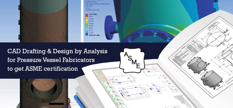
ASME certification is an exemplary achievement for pressure vessel fabricators. It is a proof of the fabricator’s superiority over others in their fraternity. The need to prove their proficiency in the market is the root cause why ASME authorization for pressure vessel fabricators across processing industry. However, attaining ASME authorization is not an easy task.
Strict Design standards and regulatory compliance are to be met for vessels may it be storage tanks, mixing tanks, processing tanks, cylinder nozzle, heads, or flanges. It requires cutting edge dedication from vessel design engineers to develop extremely accurate designs for increased operational safety.
Pressure vessel industry is the most challenging industry where safety is put above everything else. In order to get ASME certified, pressure vessel fabricators have to overcome several engineering challenges during the designing stage to ensure their end products adhere to ASME standards.
To attain this, pressure vessel fabricators should adopt 2D CAD drafts, 3D CAD modeling and optimized safe vessel designs that enable precision and error free fabrication processes down the line. It takes coordination between design engineers and fabricators to understand needs of design development and product fabrication, which significantly reduces the time to market.
State-of-the-art & robust pressure vessel design drafts with CAD
Providing accurate dimensional allowances and geometry in engineering and drafting solutions for pressure vessels is an exceptionally crucial task. However; the versatility of CAD software and the expertise of CAD designers have opened up new avenues to overcome fabrication challenges by modifying vessel designs.
Parametric CAD software empowers CAD designers to make changes in feasible designs, way before the product advances to the fabrication stage. Right from conceptual designs to final CAD drafts, from 3D CAD modeling to rapid prototyping for analysis, from fabrication drawings to installation information, parametric CAD software assists designers and fabricators to be on the same lines.
Usually vessels are made of “spherical or cylindrical geometry”. For both, spherical and cylindrical vessels, wrong material selection will lead to failure of vessels and increase safety risks. As an alternative, “spherical cylinders” have been put in practice for majority of the pressure vessels designed now-a-days. These spherical shaped cylindrical vessels have almost double the strength as compared to cylindrical pressure vessels.
CAD drafting and 3D modeling solutions played a vital role in the development of evolved vessel geometry. CAD solutions also help in designing customized pressure chambers for vessels operating at extreme pressure levels, by selecting varying materials, designs, sizes and shapes that are obtained through specialized heat treatments. However, to adopt new designs and materials, and to get ASME BPVC certification, design optimization, testing and validation in virtual environment plays a crucial role.
Full proofing of CAD models of pressure vessels using virtual simulation and analysis
Most fabricators opt for design by analysis approach, over design by rule. Design by rule involves several lists of calculations and complex formulae such as Barlow’s equations, Lame’s equations and several others for varying cylinder shapes, heads and designs for pressure vessels. These calculations often lead to errors and magnify the failure when the vessel gets operational.
Design by analysis approach, on the other hand, as mentioned in ASME Section VIII Div.2 is more consistent when referred to in terms of higher pressure and safety allowances. Employing CFD, allows pressure vessel designers to further avail fluid flow analysis in nozzles and heat transfer across the vessel and surroundings. CFD also helps pressure vessel designers in understanding functional behavior of the vessel for limiting values of pressure and temperature, through prototypes tested in virtual environment.
Apart from design and flow analysis, there are several stresses such as thermal stress, hoop stress, radial stress, etc. along with vibrations to be verified. Finite Element Analysis rules, analyze these stresses and vibrations for thick and thin vessels, for varying sheet metals to develop insights for designers and help them make informed decisions. FEA essentially delivers optimized designs and thereby avoids putting safety on line.
Conclusion
As a solution to challenges of safety risks of vessel operators and surroundings, and to get ASME certification; pressure vessel fabricators in processing industry insist upon having their designs drafted and modeled by CAD experts. With the benchmark of ASME authorization, fabricators’ needs do not end here.
Pressure vessel fabricators heavily rely on design optimization and analysis through Design by Analysis approach. It helps them stay on the same lines with design engineers to deliver safe end products. These solutions help vessel designs to evolve exactly the way they need to, from start to finish.


