
“If you’ve ever designed a ductwork routing in SolidWorks, you’d know that when you add a route and connect it to the end point of the route, you’ll encounter a twist. There are numerous other process challenges that can be enlisted. But these challenges are confined to ideal CAD environment and can be corrected at any point of time.”
When challenges emerge during or after fabrication actions get irreversible; its costs, quality, and business repercussions are cascading as a result of one single misinterpretation from fabrication drawings. These challenges usually surface due to the fact that 2D CAD fabrication drawings and 3D architectural as-built models aren’t on the same page as finely as they need to be.
Drawings eventually tend to go off sync during the process of designing to eliminate several limitations; routing issue being one of them. After all, a fabrication drawing isn’t same as 3D architectural modeling for the same building product, say ductwork.
However; AEC industry is experiencing a paradigm shift as BIM has successfully addressed these challenges. BIM made the data useful for both fabricators and architects, and also installers, foreman on the shop floor and even the MEP or sheet metal contractor.
Integrating designs to diminish silos
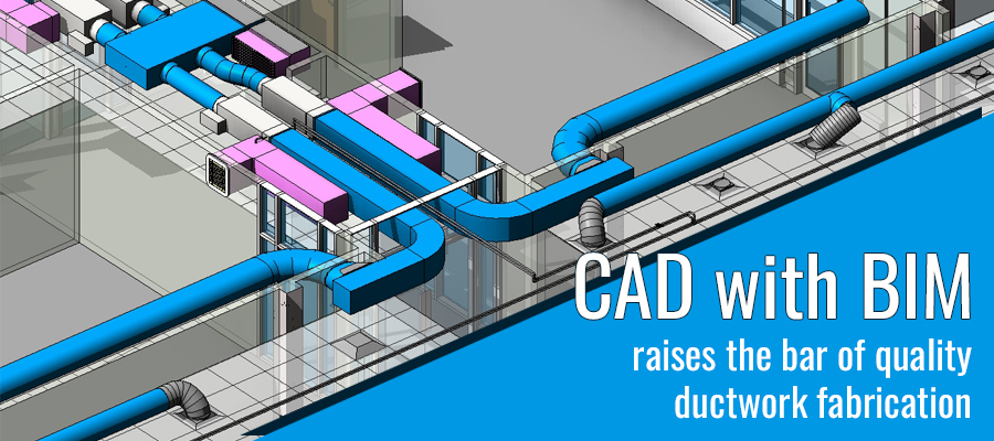
One may still come across ductwork fabricators working in silos and not on what architects have designed, causing discrepancies to on-site contractors. Upon integrating BIM process with help of Autodesk’s Revit, and fabrication drawings for ductwork; it automatically adjusts to new information.
Not only this, it also cross verifies the updates or changes with architectural plans and 3D designs. It essentially removes the barrier between 2D fabrication drawings meant for cutting and bending on shop floor and strengthens the entire process to new level.
“The fascinating thing about AEC industry and sheet metal fabrication is that they tie their roots at the same place in its most traditional form.”
Standalone CAD vs CAD and BIM
Only with CAD platforms, 2D fabrication drawings drafted in CAD along with its nesting reports are released from CAD shop only to realize that they are incorrect. The information about drawing misalignments or non-conformation to architectural requirements, are only realized when they are getting fabricated. This leaves both sheet metal contractor and the architect, in a frustrated state of re-drafting and modeling.
But when BIM is collaborated with CAD, things do not go that way and would save a lot of time to each of these professionals, and the process as a whole. It encompasses all requirements of fabricator and abides by architect’s needs too. The BIM and CAD collaboration provides a federal environment in BIM where fabrication shop floor specifications are inherited in designs, data is populated to CAD from the inception, and automated fabrication or machining processes are labelled to ensure uninterrupted fabrication.
Cumulatively, this allied approach for building products fabrication improves coordination between every discipline of construction and the process of fabrication. It results in a win-win situation for fabrication and contactors which includes meeting standards, maintaining quality, avoiding re-designing and re-fabrication, recalculation for ductwork, and saving cost and time. Even better, the alliance between BIM and 3D CAD meets the ground reality for situations at construction site and fabrication shop floor.
BIM is for simplification; it doesn’t mean overlook CAD
While one argues that CAD is inevitably the base requirement for preparing fabrication drawings, it is equally true that BIM platforms integrate these fabrication drawings to design a smart layout for the entire ductwork for the facility with architectural designs.
In practical aspects what this alliance of CAD and BIM means is that it can adjust to the contractors’ specification [or architects’ and structural engineers’ for those matters] considering fabricator’s shop floor arrangement. For example if you need to design a conical T-shaped reducer, you need the ductwork dimensions to adjust to the inlet and outlet diameters of reducer. This automatic adjustment of specification happens in CAD, for instance SolidWorks; with little or no additional mathematical calculation, and it conforms to industry standards as well.
Integrated approach for fabrication and construction in a fully-optimized BIM workflow will essentially pump out efficient fabrication products that fit perfectly into the construction designs. It is time when we move from CAD/CAM to CAD/CAM-BIM for designing/fabricating-assembling; not because it is only convenient but also because using a single file extension will save you a profound time in fetching relevant information.
A complete integration will bring you a fully responsive model of the ductwork embedded into the building envelop system and prepares itself for final fabrication work with only a little tweaking.


